
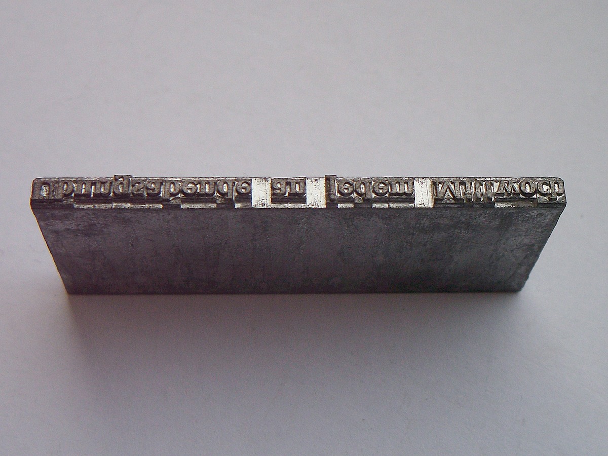
Look along the narrow top of the metal block in the photograph. The raised letters belong to one continuous piece. They are not a row of separate letters pushed together. This is a Linotype slug: a whole line of type cast in metal. The Melbourne Museum of Printing’s linecaster description identifies precisely that output, with the letterforms reversed for printing.
The less obvious part is what did not leave the machine with that line. The small moulds that supplied the characters went back into storage, ready to make different words. Follow those two paths—one towards the printed page, the other back towards the keyboard—and the machine becomes much easier to understand.

The keyboard selected moulds, not printed letters
In the Linotype account published in Theodore Low De Vinne’s 1904 book on composition, pages 403–405, each matrix is a small brass plate. A character is recessed into one edge. It is a die from which a raised printing character can be cast, rather than a piece of raised type ready to ink.
The machine holds multiple matrices for a character, so a word can contain the same letter more than once. Keys release the required matrices from channels in a magazine. They arrive in the order needed for the line, with separate spaces placed between words. At this point, the operator has composed a line of reusable moulding elements. The printing surface has still to be made.
The book’s detailed account is unusually useful here, but its authorship needs a qualification. De Vinne’s preface credits the machine-composition section to Philip T. Dodge, president of the Mergenthaler Linotype Company. It is a period technical explanation from someone with a commercial interest, rather than an independent test of the company’s claims. We can follow its described mechanism without adopting its performance claims.

The spaces physically widened
A line of words rarely happens to fill the exact width available. For a fully justified line, the gaps must take up the remaining space. On the Linotype, that adjustment had a physical form.
Mergenthaler’s 17 August 1886 patent, in its description of the expansible space-bars, describes opposing tapered pieces that slide against each other while their outside faces remain parallel. Lifting the bars expands the line. These are movable wedges, not just blank character moulds.
In the 1904 account, pages 420–421, jaws establish the length of the line. A bar pushes the spaces upwards until the assembled matrices fill the gap between those jaws. The letters do not need to become wider. The spaces change width, bringing the line to its required measure before casting.
That order matters. The machine is about to make a single solid object. Its word spacing has to be settled while the moulding elements can still move, rather than after the metal line exists.
A fresh printing surface emerged from the mould
The composed matrices are brought against a slotted mould. Their character recesses face the slot, forming the character-bearing side of the casting arrangement. A pump forces molten type metal from the melting pot into the mould and into those recesses. As it solidifies, the metal takes the form of a slug with raised characters along its edge. The museum’s short explanation of pressure die-casting corroborates this distinction between the assembled matrices and the newly cast line.
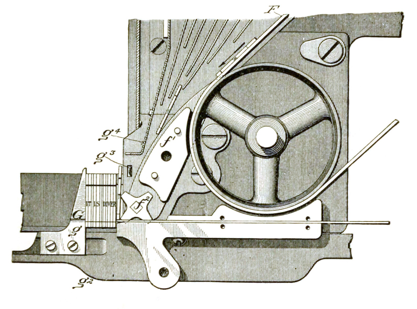
The 1904 description, pages 407–408 and 421–422, follows the next actions too. The mould wheel turns; an ejector drives the slug out through trimming knives and into a receiving galley. That galley is the tray where the completed lines collect.
Now the photograph’s single block makes sense. It is the product of a row of character recesses acting together. The matrices remain separate reusable parts; the slug carries their combined result.
The matrices needed an address for the return journey
Returning all those small plates to the top of the machine would not be enough. Each character had to reach the right storage channel. Otherwise, the next key press could release the wrong matrix.
The solution was built into their shape. In the 1904 account, pages 409–411, teeth at the top of a matrix engage a distributing bar. Different characters have different tooth arrangements. Rotating screws carry the suspended matrices along the bar, over the magazine’s channel entrances.
A matrix stays supported until it reaches the position where its teeth and the bar’s pattern allow it to drop. Gravity then takes it into its channel. The machine does not read the character recess to decide where it belongs: the tooth arrangement provides the mechanical means of sorting it.
The spaces take a different return route. The book explains that an elevator lifts the matrices away while leaving the spaces behind to return to their own magazine. Characters and word spaces have worked together to form the line, but they are separated again for reuse.
This is not a mechanism that first appears in the 1904 account. The 1886 patent’s distributing section already describes character-dependent teeth and rail sections that release matrices above the proper magazine tubes. The dated designs differ in their transport arrangements; the early patent should not be mistaken for an exact drawing of every later Linotype.
One line leaves; the next cycle continues
The returning parts explain why the Linotype is more than a keyboard attached to a casting pot. The 1904 book points out that circulating the matrices allows one line to be composed while another is cast and a third is distributed. Those stages can overlap because the moulding elements do not remain trapped in the finished printing line.
The slug has a different future. The same account, page 403, describes lines used for printing or electrotyping and remelted after use. Its metal can return to the process eventually, but it does not travel back up the distributor as a set of letter matrices.
That is the useful distinction to keep when looking at a Linotype line: the block holds the words together for printing. Behind it, the moulds have already parted company, ready to be arranged into something else.
Sources and further reading
Mergenthaler’s 1886 patent, US347629A describes the early spacing and distribution mechanisms. De Vinne’s 1904 volume, particularly pages 403–424 and the authorship credit in the preface, supplies the later technical walk-through. The Melbourne Museum of Printing’s Linotype page provides a preserved-machine description of the output and casting cycle.